Energy Analysis
When analyzing the problem that the Abbott Power Plant was facing, our team had to consult the mechanical drawings that Mike Brewer was nice enough to let us reference. These drawings, along with the fantastic schematic design that our classmate Gabe Braboy drew up, we could take a closer look at the problem; how entrained air is present in the pipe system.
Using a few different equations, we can get a good idea of the energy inside the pipe system. Bernoulli’s Equation can be used when it is assumed that the energy of the flowing fluid is conserved. The Darcy-Weisbach Friction Loss Equation can be used to calculate the head loss due to friction in a pipe. Another Darcy-Weisbach equation can be used to calculate the head less due to bends and fittings within a pipe system. The head losses due to friction are classified as “major losses” and head losses due to bends and fittings are classified as “minor losses.” Neither of these losses are more important or influential than the others; it is just a naming scheme. These three equations are listed below and will be used and expanded upon further on.

Bernoulli's Equation

Darcy-Weisbach Major Loss Equation
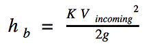
Darcy-Weisbach Minor Loss Equation
A Step-By-Step Process
In an attempt to solve Abbott's problem, our team could not rule out any possible issues that could affect the pipe system. While at the plant, a ringing or hissing noise could be heard when standing near the pipe system that has been acting up. In another part, the sound of gushing or turbulent water could be heard. These two indicators led us to conclude two things: cavitation and air entrainment. Both of which have to do with changes in pressure in the liquid.
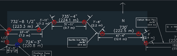
Now that the problems are identified calculations and assumptions can be made. Referencing Gabe's schematic, the principles behind the first two equations above can be used. We decided that breaking up the pipe system into sections. Each section has uniform width and material, respectively. This made it easier to make assumptions about the energy within the section, and ultimately, within the system. All calculations below are made based on perfect pipes and fittings.
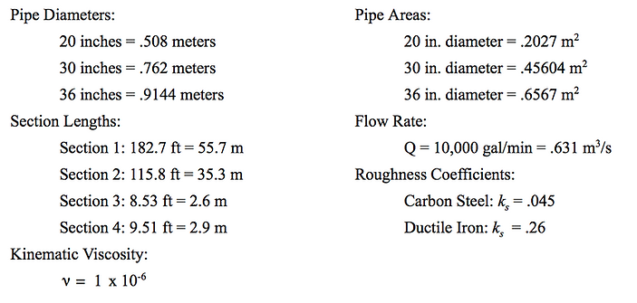
Before any calculations are made, all units must be converted into SI Units. The table below shows where all the values in the calculations can be found.
Section 1
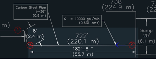
The highlighted section of the schematic is Section 1
Section 1 is a 55.7 m long Carbon Steel tube with an inner diameter of .9144 m that only receives head losses due to friction of the pipe.
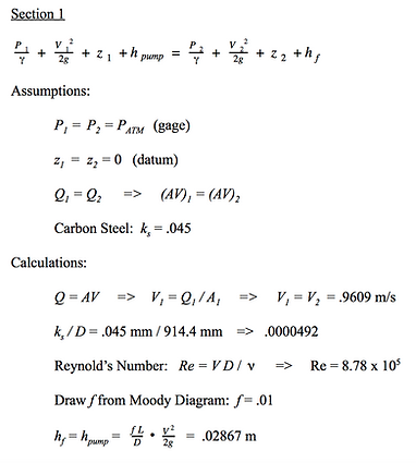
These calculations show how the assumptions made can lead directly to useful findings.
Key Values:
Gage pressures
Velocities
Major Losses = Head Gains by Pump
Section 2
The highlighted section of the schematic is Section 2
Section 2 is a 35.3 m long Ductile Iron pipe with an inner diameter of .9144 m that receives head losses due to friction of the pipe as well as changes in altitude.

Notice how there is no pump component in this section.
Key Values:
P_3 = 31.631 kPa
Section 3
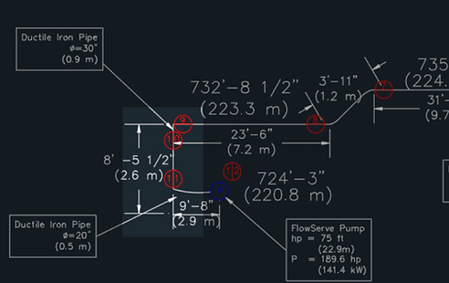
The highlighted section of the schematic is Section 3
Section 3 is a 2.6 m long vertical Ductile Iron pipe with an inner diameter of .762 m that receives head losses due to friction of the pipe as well as changes in altitude.
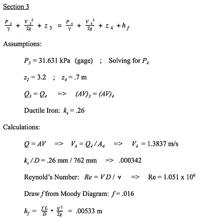
Head Losses from friction are much less since the pipe is much shorter than the two previous sections.
Key Values:
Major Losses = .00533 m
P_4 = 31.633 kPa
Section 4
The highlighted section of the schematic is Section 4
Section 3 is a 2.9 m long horizontal Ductile Iron pipe with an inner diameter of .508 m that receives head losses due to friction of the pipe.

Much like in Section 3, the head losses from friction are much less since the pipe is much shorter than the first two sections. But these losses are greater because this section has a smaller diameter and, therefore, a larger velocity.
Key Values:
Major Losses = .05077 m
P_5 = 31.135 kPa
A "Minor" Problem
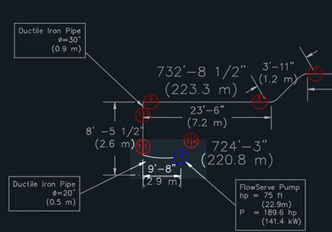
The calculations above show how the energy changes throughout the pipe system; how elevation, pipe material, and pumps can affect the pipe's pressure and velocity. What was not taken into account was how bends and fittings can affect pressure head. Now, our team assumed that the pipe system was one long pipe for simplicity in calculating the frictional losses. Below is an example of how bends and fittings can lead to losses in pressure, more commonly known as "minor losses."

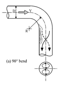
In this example, we will look at the bend that is highlighted on the schematic to the left.
Assuming that this pipe bends at a 90° and that the radius of pipe and the bend are the same and remain constant at .9114 m, we can use Darcy-Weisbach's equation for minor losses.

Virtual Labs. http://fm-nitk.vlabs.ac.in/exp4/index.html
When taking a step back and looking at the calculations major and minor losses, it can be seen that there is nothing "minor" about minor losses. The above calculation is just for one bend in the pipe system. With countless bends in the system, it can be expected that the minor losses would be great. In order to strive for a pipe system with minimal losses, a system can be devised that has the least amount of bends and the smoothest pipes in order to obtain fewer losses.
Conclusions
Based on the calculations and assumptions made above, a few conclusions can be made. When taking into account that both cavitation and entrained air are taking place, we can see possible causes of these two phenomena. Cavitation occurs when the fluid pressure of a liquid drops below the vapor pressure of said liquid. And entrained air is when air that is not supposed to system is present in the system. This could be a result of faulty junctions or fittings or leaking or cracked pipes. The result of cavitation is small microscopic bubbles that implode and cause serious damage. But not all of these bubbles pop, necessarily.
Shifting focus to cavitation and its causes, it can be seen that the water in the pipe system can be subject to this phenomena. Pipes narrowing or bending can be a cause of cavitation in a system. Other causes that could lead to cavitation pipes being too small in diameter or too high in elevation. It is usually a combination of these issues that leads to detrimental issues within a pipe system, like the one at Abbott Power Plant.