different drag forces
Please click on the above buttons to jump to that section.
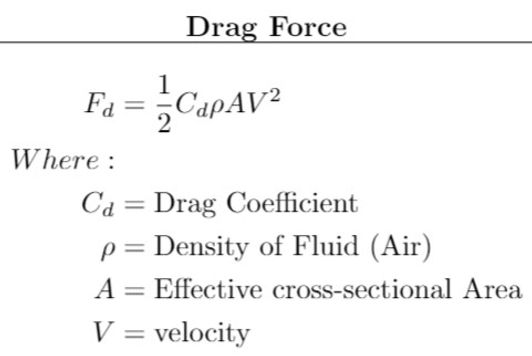
One retarding force which acts on the rocket is Drag, and while the formula is straight forward enough, computing the drag coefficient is a complex exercise when done theoretically. Use of a wind tunnel would provide an experimental method of finding the drag coefficient, but doing so without is a not fully understood field.
Modelling of the flow of fluid around the object will vary to some extent from laminar (smooth, undisturbed) to turbulent (disturbed). The complex way that the flow of the fluid interacts in the region where this change occurs is not yet modeled precisely.
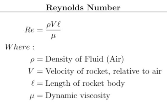
Luckily, there are some dimensionless values which can be used to guide the solution towards an assumption. The Reynolds number does exactly this. The Reynolds number provides a ratio of the inertial force on an element of fluid to the viscous force on the element.
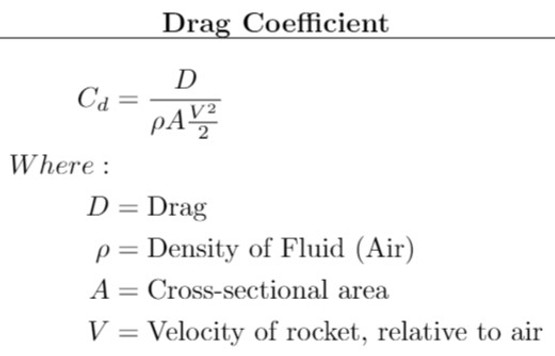
The drag coefficient is a value which is used to scale the drag force that resists the rockets motion. The difficulty of quantifying drag force comes as a result of Drag, which is controlled by density, velocity, angles, surface type, and many other variables.
At this point, the neat equation listed here is insufficient to describe the complex nature of aerodynamic drag.

To capture the drag coefficient, we must consider how each element reacts. As follows, are the most comprehensive, non-experimental values that can be computed without Computational Fluid Dynamic (CFD) software.
Each term has an associated equation, carried out below.

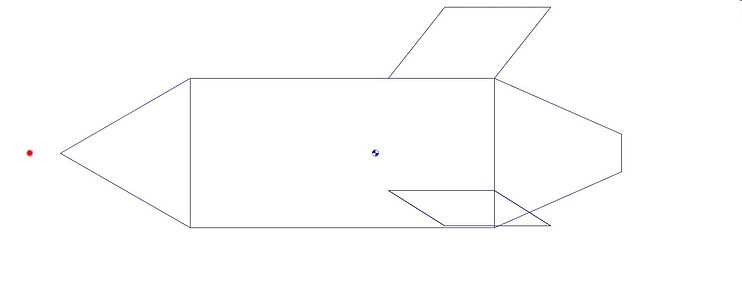
The geometry of the nose cone has the greatest effect on the aerodynamics and drag of the rocket. Some drag models use general geometry to estimate the drag coefficient for the entire rocket. Instead, this method takes into consideration how all of the pieces of the rocket work together.
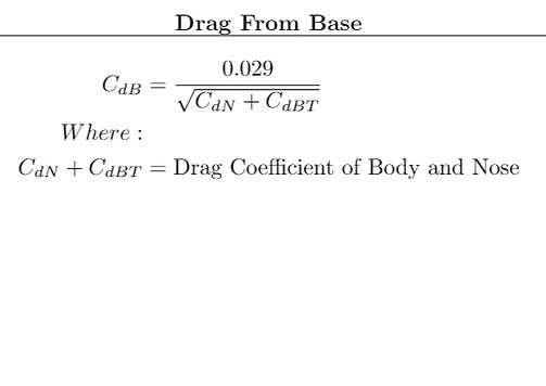
The drag due to base geometry is often neglected in pressurized rocket analysis, but it contributes nearly 30% of the total drag force.
To simplify modeling of the water rocket, the base is considered to be linear from the start of curvature to end of the nozzle.
This assumption actually leads to a potentially larger drag coefficient, because some curvature at the rockets base is desirable.
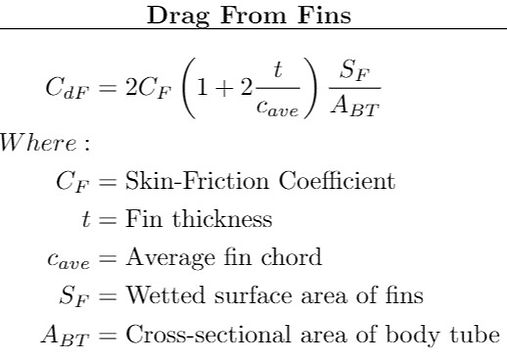
A water rocket will typically have three or four fins located near at the base of the rocket. These fins provide stability during flight, at the expense of increasing the drag coefficient. Much information exists for optimizing the fins for stability and lift, although information regarding their contribution to drag is harder to find.

The drag interface term is used to describe how the various parts of the rocket interface with one another. It is especially important to consider when a rocket is traveling with a velocity which will produce transitional flow from laminar to turbulent.

The material and finish of the material must also be considered, and this modifying term can be found in all previous formulations. Rough surfaces increase the the force required to move the object through a fluid. This term helps quantify how much the texture of the surface plays a part in the rockets aerodynamics.